How to Make Key Board Large Again S5
Keypads are a slap-up way to let users interact with your project. You can use them to navigate menus, enter passwords, and control games and robots.

In this tutorial, I'll show you lot how to setup a keypad on the Arduino. Kickoff I'll explain how the Arduino detects key presses, so I'll show you how to find the pinout of any keypad. Every bit a simple instance, I'll testify yous how to impress out the cardinal presses on the serial monitor and an LCD. Finally, I'll testify yous how to activate a 5V relay when a password is entered correctly.
BONUS: I made a quick beginning guide for this tutorial that you can download and become back to later if yous can't fix this up right now. It covers all of the steps, diagrams, and code you need to get started.
I'll exist using a 4X4 matrix membrane keypad in this article, but there's also code and wiring diagrams for 3X4 matrix keypads as well. I similar membrane mode keypads because they're thin and they besides take adhesive backing and so you tin can stick them to nigh flat surfaces. Y'all tin can as well get telephone way keypads that take thicker buttons if you like that style meliorate. Even salvaged keypads from old telephones volition work with the Arduino.
How Keypads Work
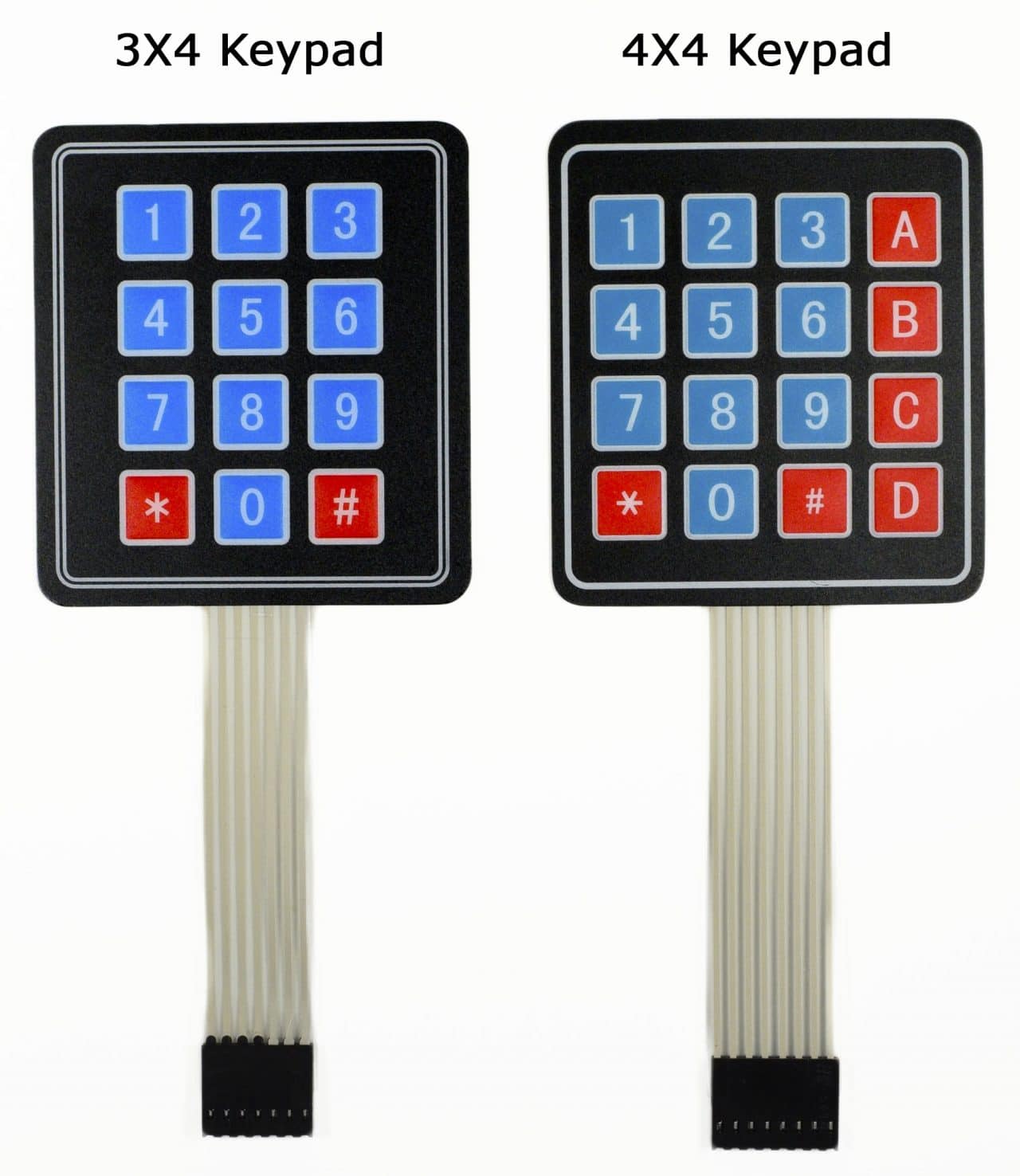
The buttons on a keypad are arranged in rows and columns. A 3X4 keypad has 4 rows and 3 columns, and a 4X4 keypad has 4 rows and 4 columns:
Beneath each central is a membrane switch. Each switch in a row is connected to the other switches in the row past a conductive trace underneath the pad. Each switch in a column is continued the same way – one side of the switch is continued to all of the other switches in that cavalcade by a conductive trace. Each row and column is brought out to a single pivot, for a total of eight pins on a 4X4 keypad:
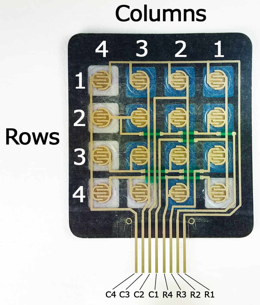
Pressing a push button closes the switch between a column and a row trace, allowing current to flow betwixt a column pivot and a row pin.
The schematic for a 4X4 keypad shows how the rows and columns are connected:
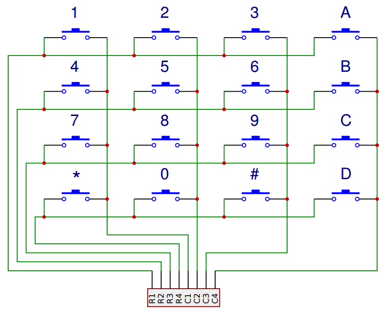
The Arduino detects which button is pressed by detecting the row and column pin that's connected to the button.
This happens in 4 steps:
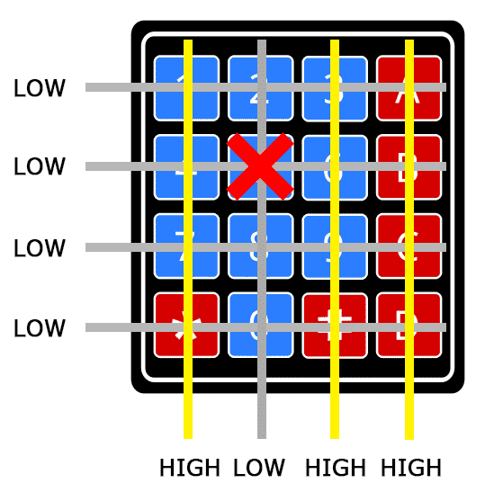
i. First, when no buttons are pressed, all of the cavalcade pins are held HIGH, and all of the row pins are held LOW:

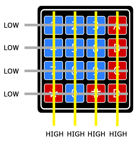
2. When a push is pressed, the column pivot is pulled LOW since the current from the HIGH column flows to the LOW row pin:
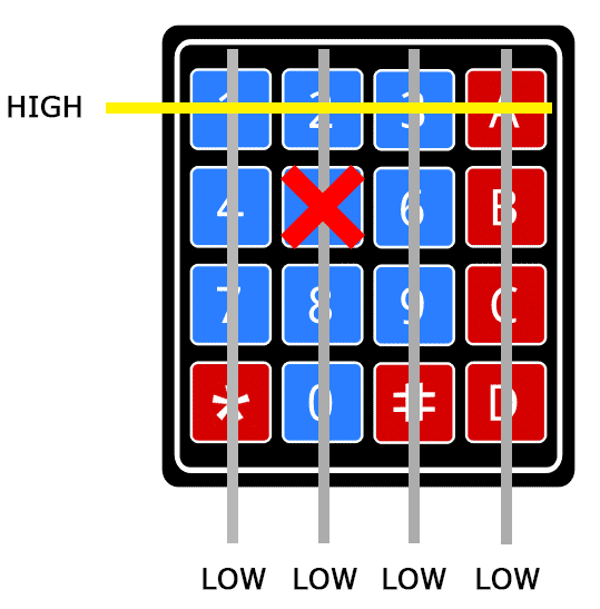
3. The Arduino now knows which column the push button is in, and then now it but needs to find the row the button is in. It does this by switching each one of the row pins High, and at the aforementioned time reading all of the cavalcade pins to observe which column pin returns to HIGH:
iv. When the cavalcade pivot goes High again, the Arduino has found the row pivot that is continued to the button:
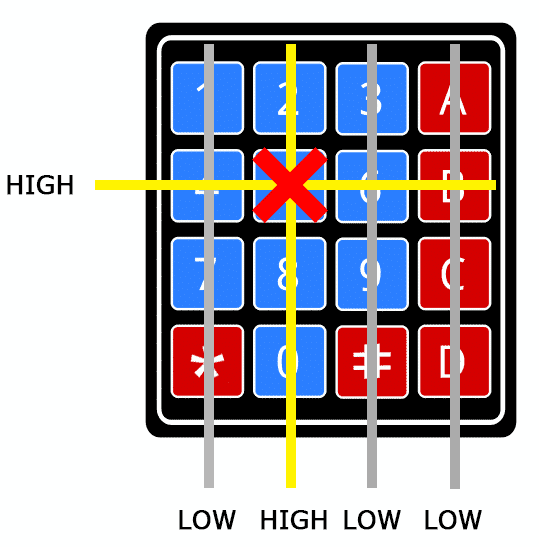
From the diagram to a higher place, you lot can encounter that the combination of row 2 and column ii could merely mean that the number v push was pressed.
Connect the Keypad to the Arduino
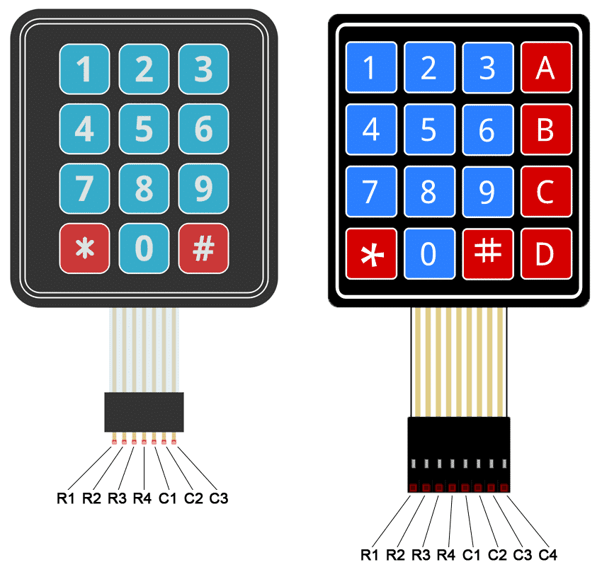
The pivot layout for nigh membrane keypads volition look similar this:
Follow the diagrams below to connect the keypad to an Arduino Uno, depending on whether you lot have a 3X4 or 4X4 keypad:
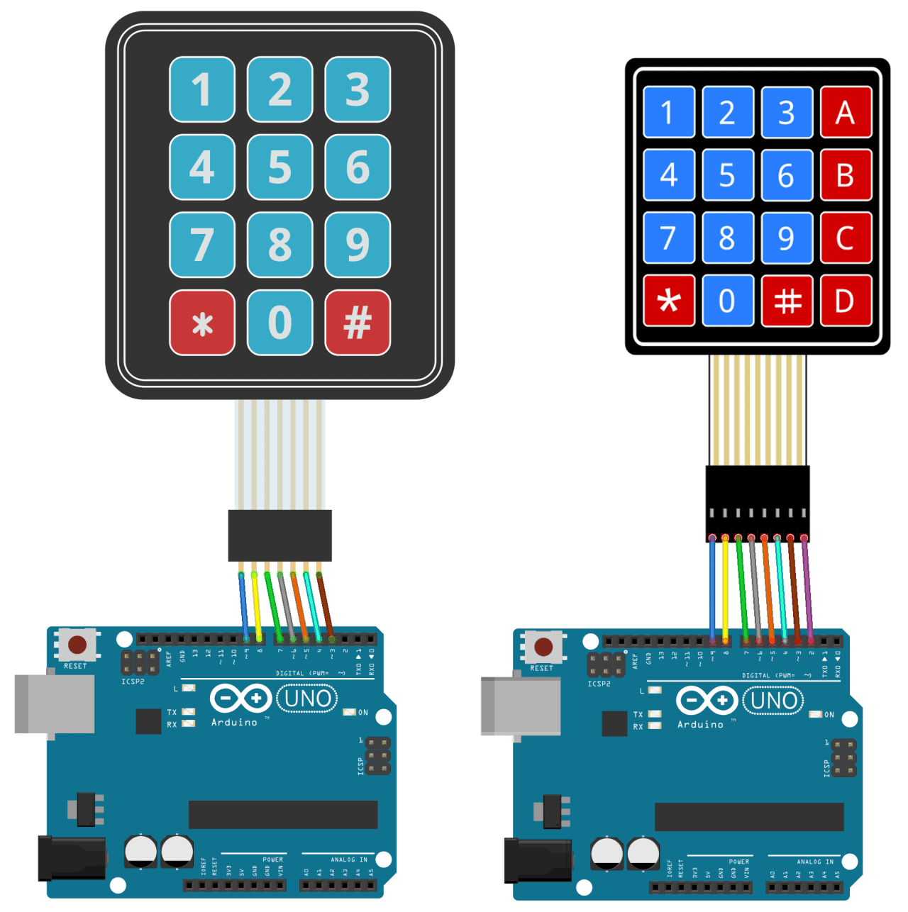
How to Discover the Pinout of Your Keypad
If your keypad's pivot layout doesn't match the ones above, y'all tin can probe the pins to figure it out. Yous'll need to build a examination excursion by connecting an LED and a current limiting resistor to the Arduino (or any 5V power source) like this:
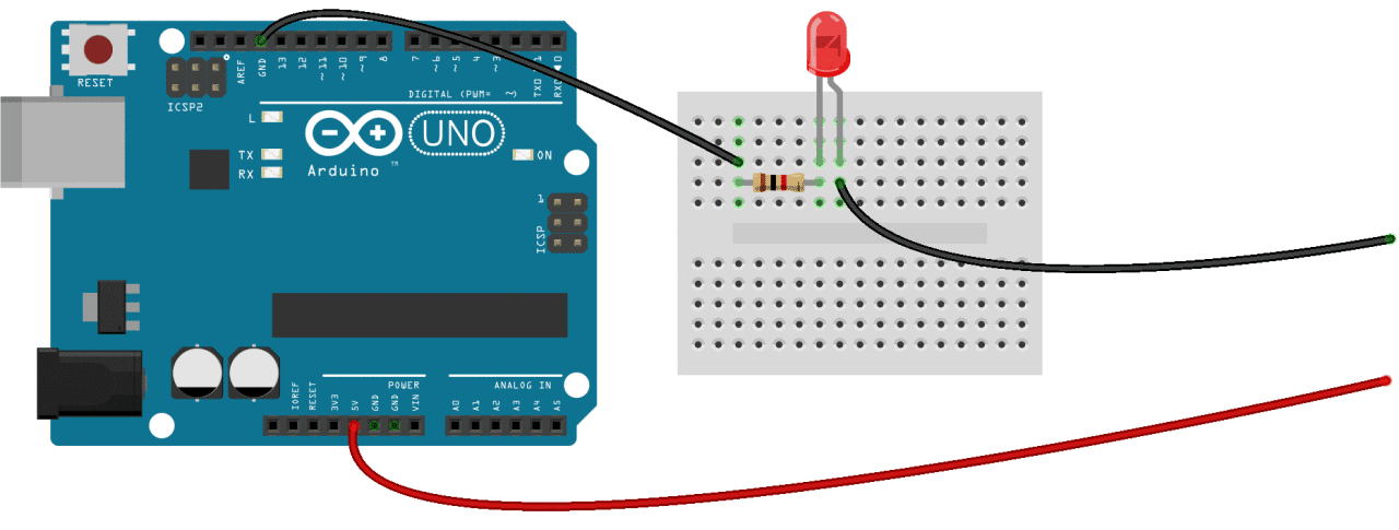
Get-go, find out which keypad pins are continued to the button rows. Insert the footing (black) wire into the first pin on the left. Press whatsoever push in row 1 and hold it down. Now insert the positive (red) wire into each one of the other pins. If the LED lights up at one of the pins, press and hold another push button in row 1, then insert the positive wire into each ane of the other pins again. If the LED lights up on a unlike pivot, information technology means the footing wire is inserted into the row ane pin. If none of the buttons in row one make the LED low-cal up, the ground wire is not continued to row 1. Now move the ground wire over to the side by side pivot, press a button in a dissimilar row, and repeat the process in a higher place until you've found the pin for each row.
To figure out which pins the columns are connected to, insert the ground wire into the pin you know is row 1. Now press and hold any 1 of the buttons in that row. Now insert the positive wire into each one of the remaining pins. The pivot that makes the LED light upward is the pivot that's continued to that push button's column. Now printing downward another button in the same row, and insert the positive wire into each one of the other pins. Repeat this process for each 1 of the other columns until you lot have each one mapped out.
Programming the Keypad
For a bones demonstration of how to setup the keypad, I'll show you how to impress each key printing to the series monitor.
Install the Library
We'll utilise the Keypad library by Mark Stanley and Alexander Brevig. This library takes care of setting up the pins and polling the unlike columns and rows. To install the Keypad library, become to Sketch > Include Library > Manage Libraries and search for "keypad". Click on the library, then click install.
The Code for a 4X4 Keypad
Once the Keypad library is installed, you can upload this lawmaking to the Arduino if y'all're using a 4X4 keypad:
#include <Keypad.h> const byte ROWS = 4; const byte COLS = 4; char hexaKeys[ROWS][COLS] = { {'one', 'two', '3', 'A'}, {'4', 'five', '6', 'B'}, {'vii', '8', 'nine', 'C'}, {'*', '0', '#', 'D'} }; byte rowPins[ROWS] = {9, 8, 7, 6}; byte colPins[COLS] = {five, 4, iii, 2}; Keypad customKeypad = Keypad(makeKeymap(hexaKeys), rowPins, colPins, ROWS, COLS); void setup(){ Series.brainstorm(9600); } void loop(){ char customKey = customKeypad.getKey(); if (customKey){ Series.println(customKey); } } The Code for a 3X4 Keypad
If you're using a 3X4 keypad, you can use this code:
#include <Keypad.h> const byte ROWS = iv; const byte COLS = three; char hexaKeys[ROWS][COLS] = { {'1', '2', '3'}, {'4', 'five', '6'}, {'seven', '8', 'nine'}, {'*', '0', '#'} }; byte rowPins[ROWS] = {9, eight, 7, 6}; byte colPins[COLS] = {five, four, 3}; Keypad customKeypad = Keypad(makeKeymap(hexaKeys), rowPins, colPins, ROWS, COLS); void setup(){ Serial.brainstorm(9600); } void loop(){ char customKey = customKeypad.getKey(); if (customKey){ Serial.println(customKey); } } Lines three and 4 in the lawmaking higher up fix the number of rows and columns on the keypad.
Lines 6-xi define which characters are printed when a particular button is pressed on the keypad. The characters are laid out but as they announced on the keypad. If your keypad has a different layout, you can ascertain which characters are printed when you press a button. For example, say your keypad has a cavalcade of letters on the left instead of the correct. Yous would but change it to this:

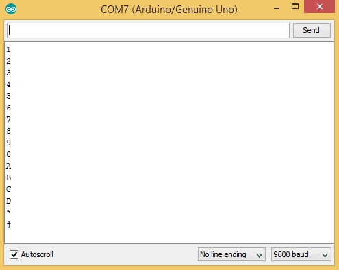
char hexaKeys[ROWS][COLS] = { {'A', 'i', '2', '3'}, {'B', 'four', '5', '6'}, {'C', '7', '8', '9'}, {'D', '*', '0', '#'} }; Later on you lot upload the code, open up the serial monitor. When you press a key, the value will be printed out:
Using an LCD with the Keypad
Now let'southward see how to print the key presses on an LCD. 4X4 keypads employ viii pins and 3X4 keypads utilize 7 pins. That takes up a lot of pins, so I'm going to employ an I2C enabled LCD considering it merely needs 4 wires to connect to the Arduino.
Install the LiquidCrystal_I2C Library
To use an I2C enabled LCD on the Arduino, yous'll demand to install the LiquidCrystal I2C library by Marco Schwartz. This library is nice because it includes nigh of the functions available in the standard LiquidCrystal library. To install it, download the Zip file beneath, so go to Sketch > Include Library > Add .ZIP Library:
![]() LiquidCrystal I2C.zip
LiquidCrystal I2C.zip
The Wire Library
The Wire library is needed to add support for I2C communication. It comes packaged with the Arduino IDE, so there's no need to install it. But if for some reason it'south not installed on your system, get to Sketch > Include Library > Manage Libraries and search for "wire" to install it.
Connect the Keypad and LCD
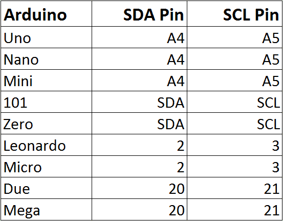
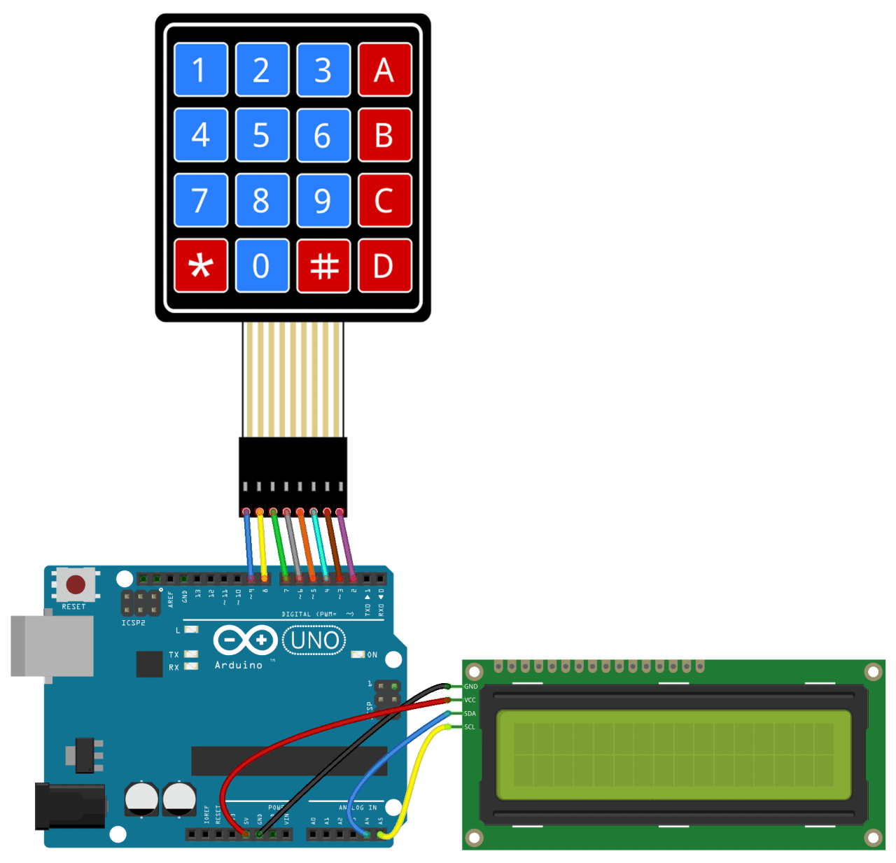
Once the libraries are installed, connect the footing and Vcc pins of the LCD to the Arduino, then connect the LCD'southward SDA and SCL pins according to the table below for the dissimilar Arduino boards:
So connect the keypad to the Arduino. It should expect something similar this (for an Arduino Uno):
Code for Output to an LCD
Once everything is connected, upload this code to the Arduino:
#include <Wire.h> #include <LiquidCrystal_I2C.h> #include <Keypad.h> const byte ROWS = iv; const byte COLS = 4; char hexaKeys[ROWS][COLS] = { {'one', '2', '3', 'A'}, {'4', 'five', '6', 'B'}, {'7', 'eight', 'ix', 'C'}, {'*', '0', '#', 'D'} }; byte rowPins[ROWS] = {9, 8, 7, 6}; byte colPins[COLS] = {v, four, 3, ii}; Keypad customKeypad = Keypad(makeKeymap(hexaKeys), rowPins, colPins, ROWS, COLS); LiquidCrystal_I2C lcd(0x21, sixteen, ii); void setup(){ lcd.backlight(); lcd.init(); } void loop(){ char customKey = customKeypad.getKey(); if (customKey){ lcd.articulate(); lcd.setCursor(0, 0); lcd.print(customKey); } } You'll need to add together the I2C accost of your LCD on line xx:
LiquidCrystal_I2C lcd(0x21, sixteen, ii);
The I2C address of my LCD is 0x21, but your's will probably be different. The I2C address of your LCD should exist provided in the datasheet, only if not, y'all tin can notice it by running this I2C_Scanner sketch.
Utilize a Password to Activate a Relay
One of the almost useful applications of a keypad is to apply it for keyed entry. You can prepare a password and have the Arduino activate a relay or some other module if the password is correct. The post-obit code will actuate a 5V relay when the countersign is entered correctly:
#include <Wire.h> #include <LiquidCrystal_I2C.h> #include <Keypad.h> #define Password_Length 8 int signalPin = 12; char Data[Password_Length]; char Master[Password_Length] = "123A456"; byte data_count = 0, master_count = 0; bool Pass_is_good; char customKey; const byte ROWS = 4; const byte COLS = iv; char hexaKeys[ROWS][COLS] = { {'1', 'two', '3', 'A'}, {'four', '5', '6', 'B'}, {'vii', '8', '9', 'C'}, {'*', '0', '#', 'D'} }; byte rowPins[ROWS] = {9, eight, 7, 6}; byte colPins[COLS] = {5, iv, three, ii}; Keypad customKeypad = Keypad(makeKeymap(hexaKeys), rowPins, colPins, ROWS, COLS); LiquidCrystal_I2C lcd(0x21, xvi, 2); void setup(){ lcd.init(); lcd.backlight(); pinMode(signalPin, OUTPUT); } void loop(){ lcd.setCursor(0,0); lcd.impress("Enter Password:"); customKey = customKeypad.getKey(); if (customKey){ Information[data_count] = customKey; lcd.setCursor(data_count,1); lcd.impress(Information[data_count]); data_count++; } if(data_count == Password_Length-ane){ lcd.clear(); if(!strcmp(Data, Master)){ lcd.print("Right"); digitalWrite(signalPin, HIGH); delay(5000); digitalWrite(signalPin, LOW); } else{ lcd.impress("Incorrect"); delay(1000); } lcd.clear(); clearData(); } } void clearData(){ while(data_count !=0){ Information[data_count--] = 0; } return; } Y'all can change the password on line 10 by replacing the 123A456 text with your own password:
char Master[Password_Length] = "123A456";
The length of the password needs to be set on line five:
#ascertain Password_Length eight
The countersign in the case in a higher place is only vii characters long, but the password length is actually one greater than 7 because in that location is a zero character added to the end of the cord. For example, if your countersign is 5 characters long, yous would enter 6 for the password length.
The output pivot that activates the relay is divers on line 7:
int signalPin = 12;
Later connecting everything to the Arduino, you lot should have something that looks like this:
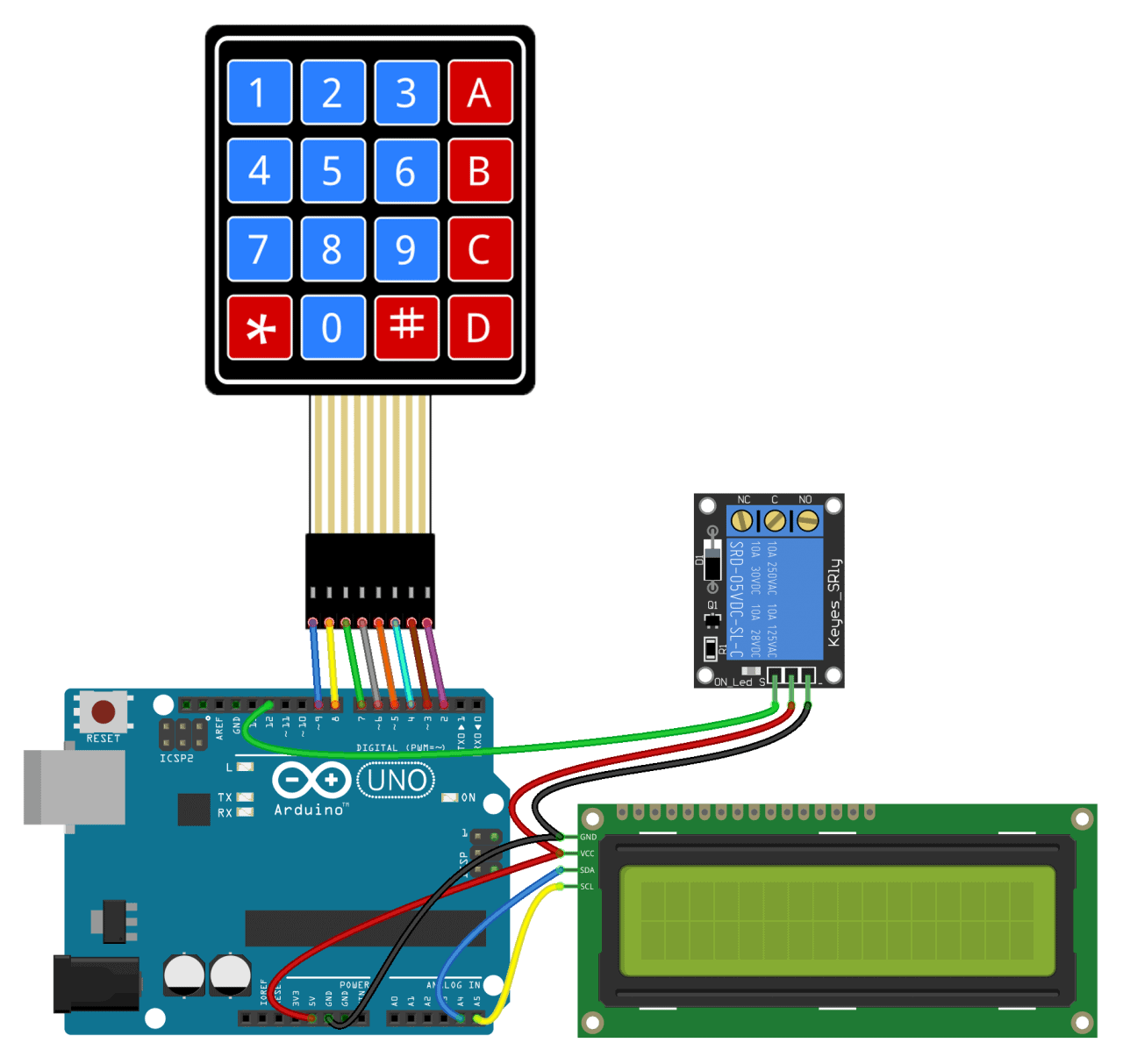
Well that's nigh it. It's not hard to set a keypad at all. I call up with a fiddling trial and error you should be able to change the code above to work with most of the projects you'd want to use a keypad for. But if y'all run into problems, just allow united states of america know in the comments and we'll try to help you out.
Source: https://www.circuitbasics.com/how-to-set-up-a-keypad-on-an-arduino/
Post a Comment for "How to Make Key Board Large Again S5"